Introduction
The Embedded System Lab setup
This modular lab course gives an introduction to selected aspects of analog signal processing and data acquisition techniques. An embedded system running user programs written in Python and/or C is used to directly interact with the experiment module’s hardware . The embedded system hardware is based on a Raspberry Pi single board computer which is mounted to a custom base board. The base board allows access to various interfaces (UART, I2C, SPI etc.) which are implemented via the general purpose IO ports (GPIO). In addition, the base board features a fast 12-bit ADC, which allows the Raspberry Pi to be used as a simple oscilloscope to sample waveforms for further processing, documentation, and analysis.

Embedded System Lab base board with a Raspberry 4 module
The individual experiments are featuring dedicated add-on boards (modules) which are controlled from the Raspberry Pi via an SPI bus and other GPIO signals. The fast ADC on the base board will be used to record analog waveforms and also other lab equipment like power supplies can be remotely controlled with the Raspberry Pi. Here is an overview of currently available add-on modules/experiments:
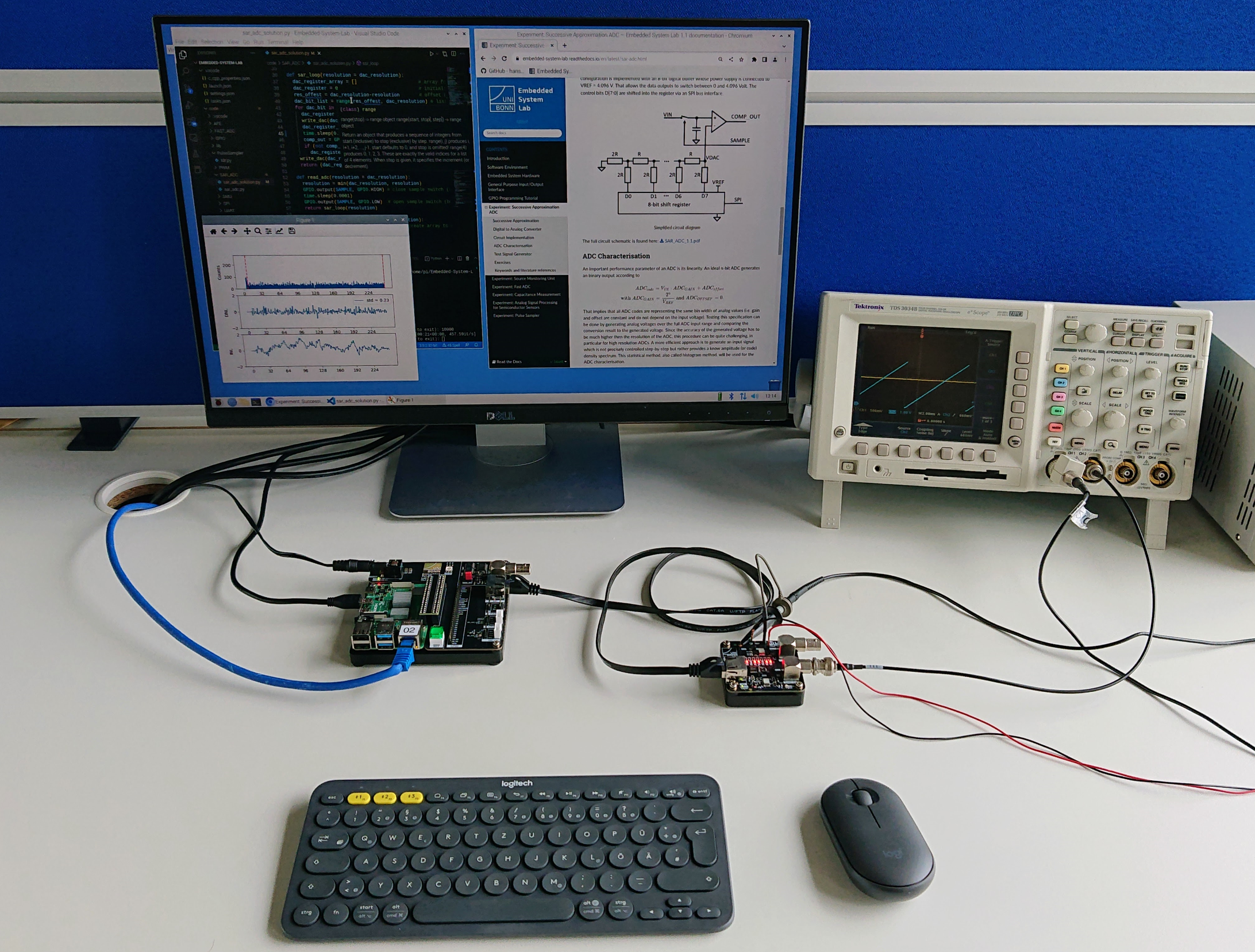
Analog-to Digital Conversion using Successive Approximation
This module implements a 8-bit Successive-Approximation-Register ADC (SAR ADC) which consists of a sample and hold input stage, a comparator, and an 8-bit resistor ladder DAC. The user will write the code to implement the SAR logic which controls the sampling stage and DAC and develop scripts for automated measurements to characterize the ADC’s various performance parameters (linearity, noise, etc.).

Successive-Approximation-Register ADC Module
Device Parameter Extraction with I-V Curves
An important parameter of electronic devices is their current-voltage characteristic. The most simple one is the linear I-V curve (resistance) of a resistor. For active devices like transistors more complex curves parameterizing their transimpedance and transconductance are of interest. To measure these parameters typically a programmable voltage source is used which is capable of precisely monitoring the current. The SMU (source monitoring unit) module with two channels which will be used to measure and analyze various MOSFET parameters (Id vs Ugs, transconductance, output impedance etc).

Source Monitoring Module
Analog Signal Processing Chain for Particle Detectors
In this experiment a typical analog signal processing chain for semiconductor detectors will be introduced and analyzed. The user will measure the system response to calibration signals and measure the electronic noise as a function of various sensor and circuit parameters. Advanced users can build a Multichannel-Spectrum-Analyzer (MCA) with this module to measure the energy spectrum of radioactive sources.

Analog Front-end Module
Capacitance Measurement
The capacitance of a semiconductor detector is an important parameter for the sensor performance. This module measures the capacitance of a sensor diode as a function of the applied bias voltage (CV measurement). In this experiment the user will developed scripts to control the capacitance measurement circuit, read the analog measurement value, and remote-control a power supply for the detector bias.

CV-Meter Module
Transmission Line Characterisation with the TDR Method
High-speed signals need controlled impedance lines (transmission lines, TML) to maintain their signal integrity. So called time-domain-reflectometry (TDR) is a known method to characterize TMLs. This module implements a TDR measurement circuit which generates a very fast pulse to be coupled to a TML-under-test. The reflected waveform is recorded with digital serial analyzer (DSA) which will be controlled by the user code.

Fast Pulse Sampler
In the course of each experiment, the user will:
Develop scripts to control the given module,
Acquire various measurement data and
Document and analyze the measurements.
Each experiment comes with basic code examples which can (but don’t have to) be used to get started. The example code is mainly written in Python but C examples are also given in some places. The experiments can be done in arbitrary sequence but is is recommended to start with the GPIO Basics tutorial.